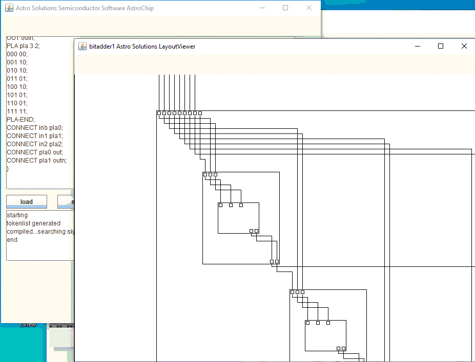
ASTROCHIPLAYOUTDB1.4 23.8.2020
The chips described and simulated with AstroChip can be visualized
with AstroChipLayoutDB1.4. The elements of the chip are arranged in
a row from the upper left side of the chip to the lower right side.
Elements can be and-, or- or inv-logics or PLAs. You can organize
logical elements in a group. If outputs and inputs in the row are
connected, the the application can connect them. The results are very
large chips. It is possible to move the elements and then the program
tries to connect them again. This can be done to reduce the size
of the chip. If the chip is small, the arrangement in a row can
make sense for the improvement of the undestanding of the data flow.
If they are defined as a MODULE in AstroChip,
all MODULEs of the same type are changed the same way after element moves.
If you move over an element with the mouse, you get an element information
from the application.

